Now that the constituent parts have been identified which could be formed into lumped elements, the values of these elements have to be calculated. These are values for the R, L and C components that are calculated from the physical dimensions of these parts. There are different empirical formulations available for some of the common shapes found. In the Ole Wolff driver that’s being studied here, the parts identified are slits, cylindrical vents and cavities with a finite volume. The empirical relations for these shapes as defined in Borwick[1] are as follows. The conditions for which these relations are defined are listed at the bottom of the same page under Figure 14.2.
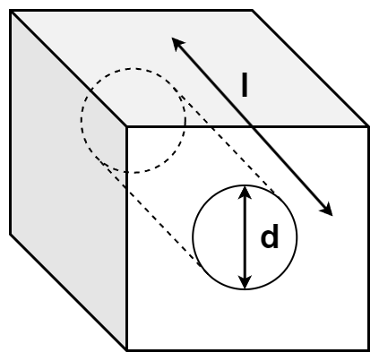
Hole/Cylindrical vent
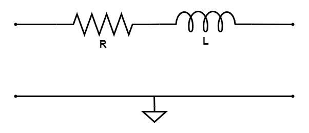
A vent with a circular cross-section is modelled as an acoustic mass which translates to an inductor in the lumped circuit. However, a resistor is added in series to this inductor to model the thermo-viscous losses at the boundaries of the circular vent. This happens due to air particles sticking to the surface of the body on the inner walls of vent which refuse to move freely as compared to the air molecules in the other parts inside the vent. The friction offered by these stuck molecules lead to losses in heat and due to the viscous nature of particles there are losses, which are in total addressed by the term ‘thermo-viscous’ losses.
The physical dimensions of the vent structure as in the illustration are used to find the corresponding values of the acoustic mass and the losses which are given by the empirical relations for L and R given below. Note the term empirical here. These expressions are not expected to provide accurate values of lumped components. However, these are good enough starting guesses which are to be used to estimate the more appropriate values for these components by curve fitting, based on the measurement data of the driver that is available.
$R = \frac{8 \cdot \eta \cdot l}{\pi \cdot \left ( \frac{d}{2} \right )^4}$
$L = \frac{\rho \cdot l}{S} = \frac{\rho \cdot l}{\pi \cdot \left (\frac{d}{2} \right )^2}$
The R and L components in the circuit are to be connected in series as shown below.
Rectangular Slit
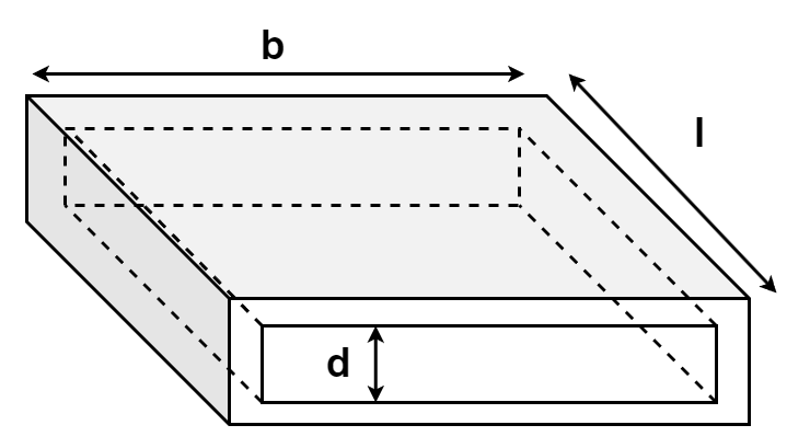
The next shape of interest is a rectangular slit as seen in the illustration below. The empirical expressions given below relate the equivalent lumped component values to the physical dimensions. Once again, a series combination of an acoustic mass (inductance L) and acoustic losses (resistor R) are used to represent a slit of this type. It is worth noting that the expression given below is for the condition where d < b. For other dimensional relationships, the expressions could vary or the same expression could be used with re-arranged dimensions based on the available structural shape and most importantly, by always considering the direction of sound propagation through the slit. These expressions apply only if the sound propagates through the cross-section from the entry slit, onto the other end of the section.
$L = \frac{6}{5} \cdot \frac{\rho \cdot l}{b \cdot d}$
$R = \frac{12 \cdot \eta \cdot l}{b \cdot d^3}$
The R and L components in the circuit are to be connected in series as shown below.

Cavity with a volume, V
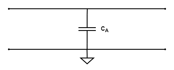
An air filled cavity of volume, $V$, with rigid walls is modelled as an acoustic compliance whose value is obtained as follows. The corresponding electrical component in the model circuit is a capacitor, as seen in the figure below. Note, that one of the terminals is grounded and this is a necessary condition for modelling a cavity compliance. This is under the assumption that the pressure on the inner walls of the cavity is 0 (Zero) due to the condition that the walls are assumed to be perfectly rigid. A zero acoustic pressure would relate to a zero voltage in the Impedance analogy and hence grounding one of the terminals to ground.
Error: The RIGID wall condition does NOT equate to the acoustic pressure being ZERO. It is the particle velocity that is zero at the rigid wall. Detailed explanation for this is provided in the next post.
$C_A = \frac{V}{\rho \cdot c^2}$
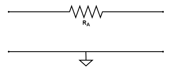
Mesh resistance
Meshes/fabrics used to add damping to the system are modelled as an acoustic loss element which relates the Specific Acoustic Resistance, $R_S$, in $Rayls$ and the Surface Area of the mesh, $S$, in $m^2$ as follows.
$R_A = \frac{R_S}{S}$
Radiation Impedance
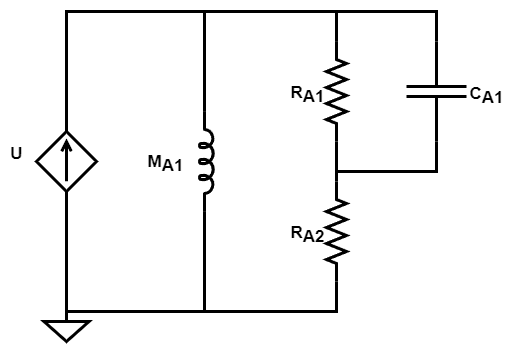
A plane circular piston of radius, $a$, radiating into free-field faces an acoustic load acting on it due to the air in the free-field. This load has a complex behavior which is modelled as the circuit seen above as given in Figure 2.9 of section 4.19 in Beranek and Mellow[2]. Empirical relations for each of the components’ values in the circuit above are derived for 2 edge conditions, one for the case where the piston is mounted on an infinite baffle and the other for the case when there is no baffle and the piston is mounted at the end of a long tube. In the real field, the measurement conditions could drastically differ since these 2 ideal conditions are almost impossible to create while measuring. Any obstruction or object anywhere close to the driver affects the sound field emanating from the driver diaphragm. These empirical relations are even derived based on the condition that the wavefront emanating from the diaphragm is perfectly spherical which leads to solutions to the wave equation which are Bessel functions. So any object around or near the driver obstructs the sound field and the free-field condition is no longer valid. A free-field is when there are absolutely no reflections from the sound field. Even measurement microphones used to capture the sound field of the driver affect the sound field due to diffractions and reflections caused by the microphone body when sound hits it.
Piston on a baffle
$M_{A1} = \frac{8 \cdot \rho}{3 \cdot \pi^2 \cdot a}$
$R_{A1} = 0.441 \frac{\rho \cdot c}{\pi \cdot a^2}$
$R_{A2} = \frac{\rho \cdot c}{\pi \cdot a^2}$
$C_{A1} = 5.94 \frac{a^3}{\rho \cdot c^2}$
Piston at the outlet of a long tube (No baffle)
$M_{A1} = 0.6133 \frac{\rho}{\pi \cdot a}$
$R_{A1} = 0.5045 \frac{\rho \cdot c}{\pi \cdot a^2}$
$R_{A2} = \frac{\rho \cdot c}{\pi \cdot a^2}$
$C_{A1} = 0.55 \cdot \pi^2 \cdot \frac{a^3}{\rho \cdot c^2}$
What next?
The next step would be to apply these relations and the equivalent circuits for each of the structural shape types discussed above to the ones we have identified for the Ole Wolff driver under investigation and see how to connect them together to develop the complete driver lumped model.
1 Comment