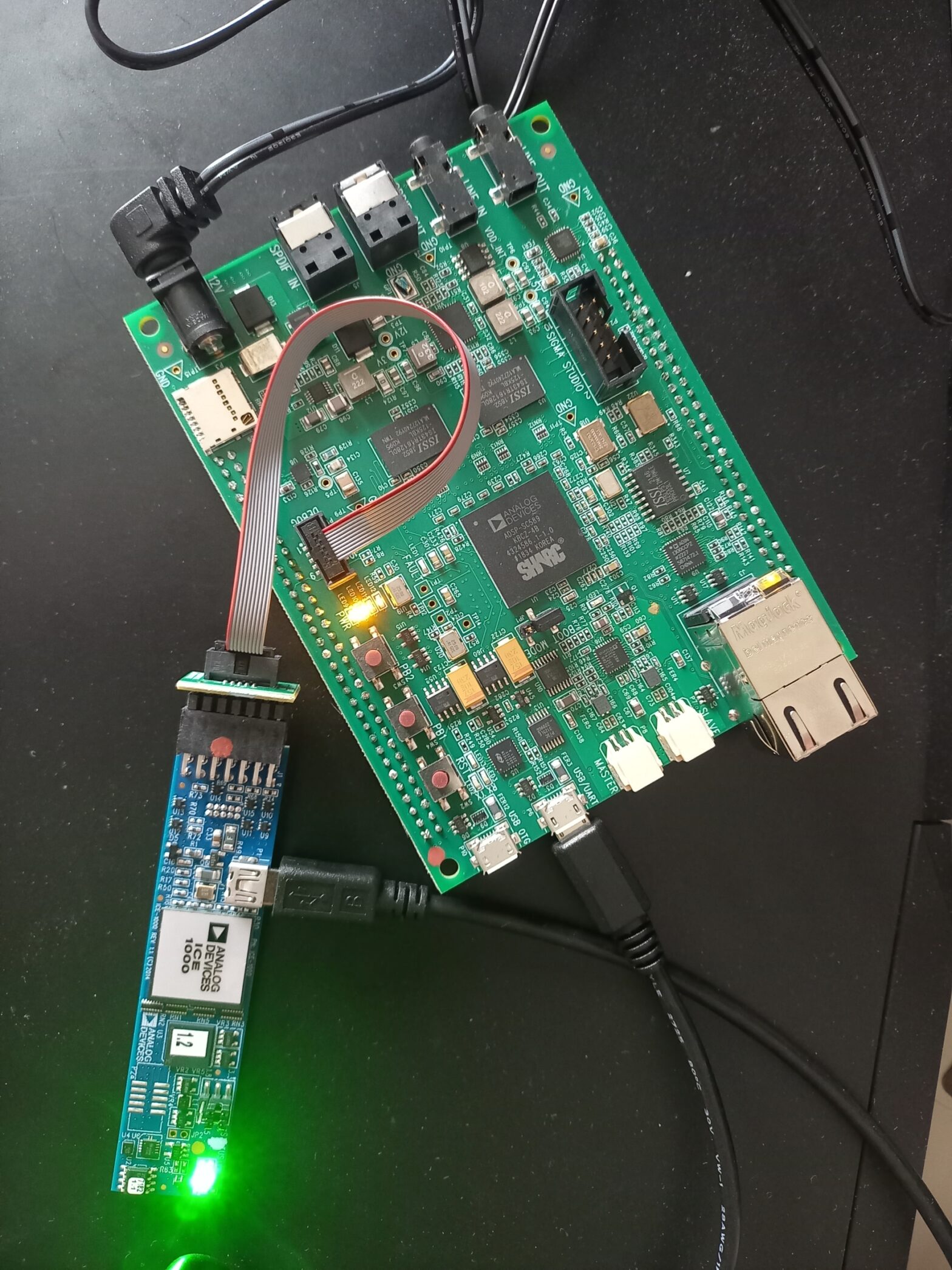
For some time now, I have been wanting to dabble with some serious DSP hardware at the chip level so that, one day, I can build my own hardware for implementing active crossovers, EQs, filters, etc. for loudspeakers, room correction systems, etc. I wanted to go for the most powerful and popular solution in the…More
Lumped Element Modelling – Micro-speakers #11
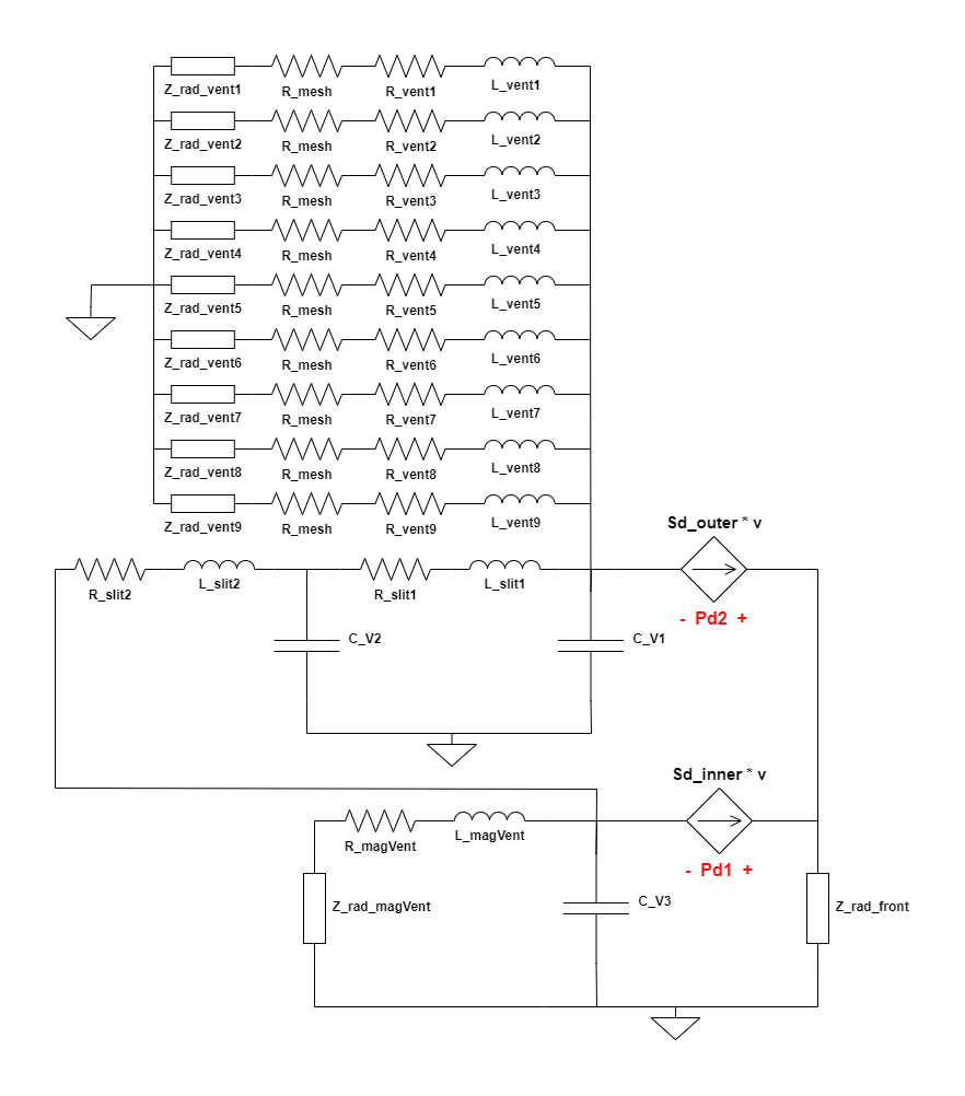
Now that the complete circuit representing the lumped model for the Ole Wolff driver in consideration has been developed, we need to find the component values for each of the R, L and C components in the circuit so that it fully mimics the behavior of the actual driver and matches the measured response. However,…More
Lumped Element Modelling – Micro-speakers #10
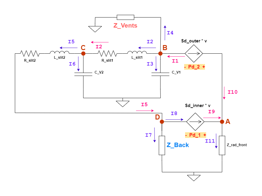
In the previous post, a block diagram of the acoustic model of the driver was prepared and introduced. It’s time to convert it into an electrical circuit which would be the acoustic part of the lumped model circuit of the Ole Wolff driver being studied here. The following generic model circuit was shared in one…More
Lumped Element Modelling – Micro-speakers #9
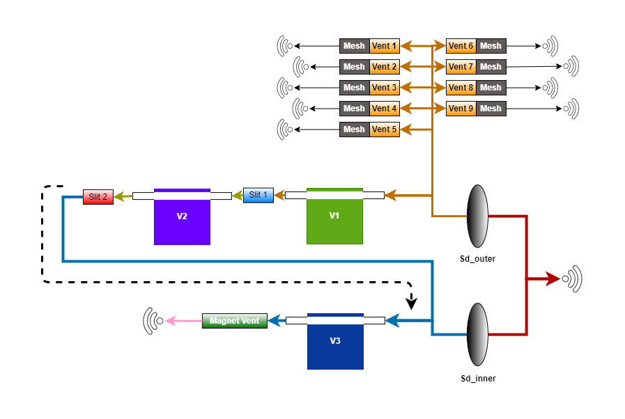
In the previous post, how different elementary structural shapes/forms are represented in the lumped electrical circuit was discussed. The mathematical expressions for calculating corresponding component values were also discussed. It’s time to advance further into converting the shapes/parts identified in the Ole Wolff driver that’s being studied here and see how they connect with each…More
Lumped Element Modelling – Micro-speakers #8
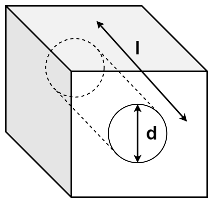
Now that the constituent parts have been identified which could be formed into lumped elements, the values of these elements have to be calculated. These are values for the R, L and C components that are calculated from the physical dimensions of these parts. There are different empirical formulations available for some of the common…More
Lumped Element Modelling – Micro-speakers #7
In the previous posts, the electro-mechanical sections of the driver’s lumped element were characterized and the parameters estimated from measurement data (manufacturer provided), by curve fitting. Now that, that is fixed, it’s time to look at the acoustical part of the model circuit. Generally, the acoustical section of the model is characterized as a Controlled…More
Lumped Element Modelling – Micro-speakers #6
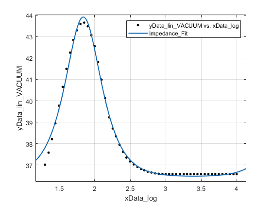
In the previous blog post, while fitting the transfer function equation to the measurement data, I emphasized on the importance of having realistic and sensible Starting Values for the fitting algorithm to achieve good fit while also estimating sensible values of parameters. This is always easier said than done. I have always felt that, one…More
Lumped Element Modelling – Micro-speakers #5
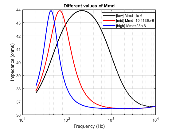
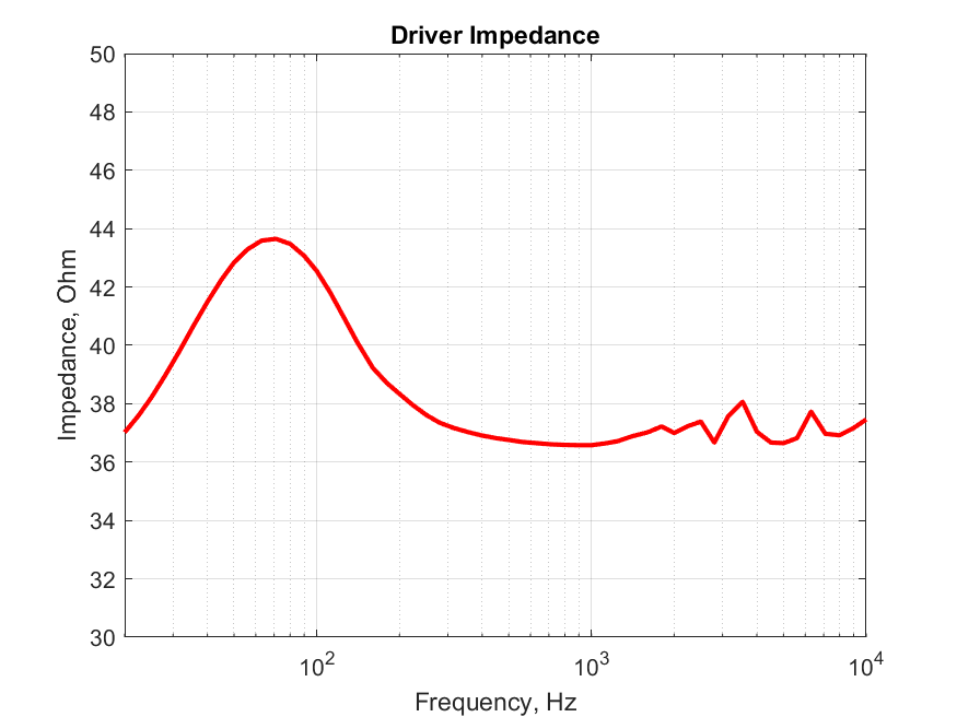
In the last blog post, I said, the DC resistance of the driver as specified by the manufacturer ( $34 \Omega$) could be incorrect and could be a target spec value which they abide by for this product. Electro-acoustics simulation expert, Rene Christensen of Acculution (the same friend I was referring to, in my previous…More
Lumped Element Modelling – Micro-speakers #4
In the previous post, I derived the circuit equations for the electro-mechanical part of the lumped model and derived the voltage-current transfer function, $G_{ui}$, which is also the Impedance of the driver. Since we needed to find the values of the constituent elements/parameters of the transfer function equation, which invariably are the T/S parameters of…More
Lumped Element Modelling – Micro-speakers #3
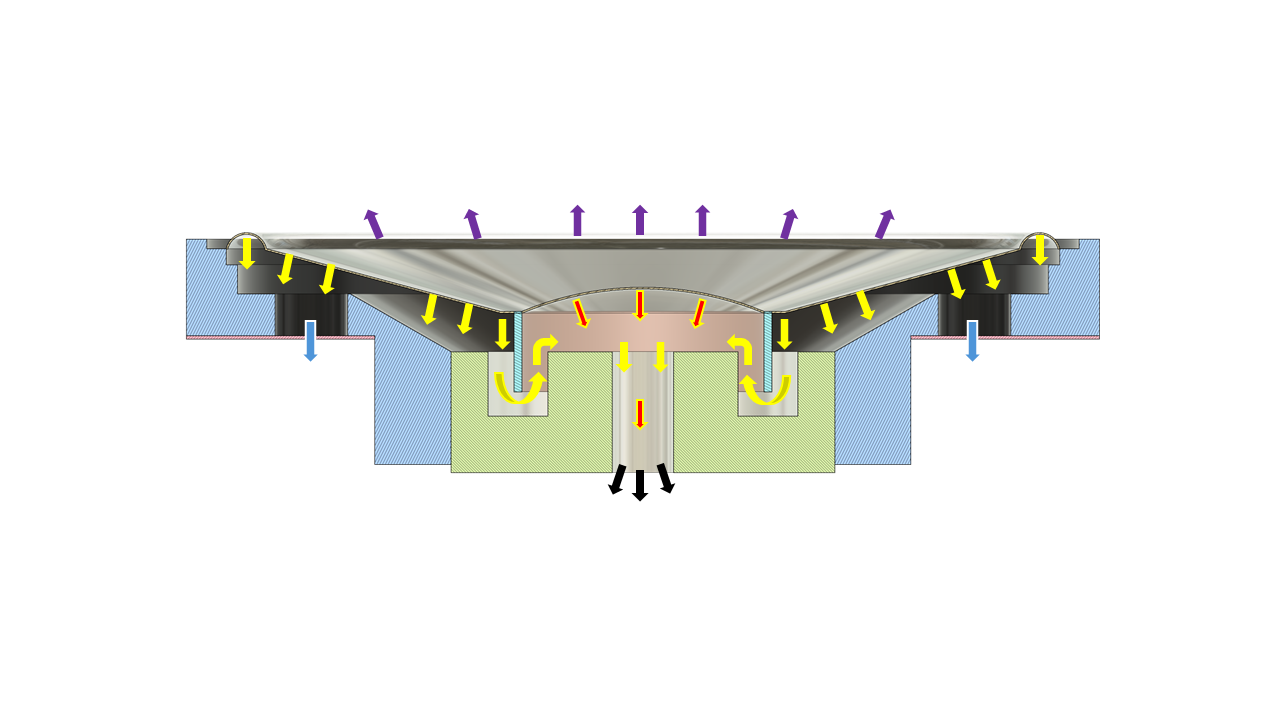
It’s time to look at the driver’s constituent parts one by one and see how and what they translate into in the lumped model. As I mentioned in the first part of this post already, the model I intend to develop would be more detailed in the acoustic section. The electrical and mechanical sections of…More
