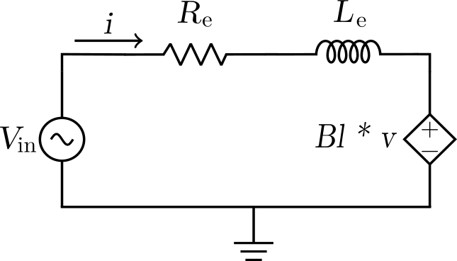
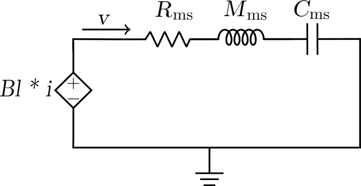
It’s time to look at the driver’s constituent parts one by one and see how and what they translate into in the lumped model.
As I mentioned in the first part[1] of this post already, the model I intend to develop would be more detailed in the acoustic section. The electrical and mechanical sections of the model are based on the generic loudspeaker model as shown below. This would mean, the electrical section models the following,
| $R_e$ | Electrical DC resistance of the voice coil |
| $L_e$ | Inductance of the voice coil |
The mechanical section models,
| $M_{ms}$ | Mass of driver diaphragm along with voice coil and air load |
| $C_{ms}$ | Mechanical compliance of driver suspension |
| $R_{ms}$ | Mechanical resistance of total driver losses |
Since there are multiple physics involved in the operation of a speaker driver/transducer, there are transduction elements between circuit sections depicting each of the physics domain that need to be modelled too. For this purpose, I would be using Controlled Voltage and Controlled Current sources. To ensure the coupling between domains happens at the right magnitudes, we introduce what is called a Transduction Factor. For the electrical to mechanical domain coupling/transduction, the transduction factor used is,
| $Bl$ | Magnetic Force Factor |
For the coupling between mechanical and acoustical domains, the factor would be,
| $Sd$ | Effective Radiation Area of the speaker diaphragm |


The transduction between electrical and mechanical sections of the model is represented by the Dependent Voltage sources in both circuits which are coupled via the Magnetic Force Factor, $Bl$, as the transduction factor, as seen in the circuits above. I have omitted the dependent voltage source element on the mechanical circuit which shows the coupling to the acoustical domain. This is only temporary. I will modify this circuit to incorporate it at a later stage. This is because currently we do not have the Thiele Small parameters of the Ole Wolff driver that is being studied here. The datasheet of the product does not reveal that information. So, I have been thinking about drawing out the circuit equations for the electrical and mechanical circuits first to obtain the voltage-current transfer function, which is the Electrical Impedance, and then obtain the parameters by a curve-fitting procedure. This is since we have the Impedance chart made available by the company on the product page.
The mechanical circuit without the acoustic transduction voltage source element included, represents the driver operated in Vacuum. Hence $M_{ms}$ would ideally be have to replaced with $M_{md}$ since the former represents the total moving mass of the diaphragm including the mass of the air load, while the latter is the moving mass of the diaphragm alone, without the air load.
We only have one impedance measurement data available with us (as seen on the product website). In that case, how do we know if the impedance data is from a vacuum measurement condition or from an in-air scenario?
This is an important consideration to be looked into. Generally the first primary/dominant peak is purely from the driver’s moving parts which resembles closely to the impedance of the driver measured in vacuum. However, when the same driver is measured in air, the resonance frequency of the peak shifts lower as compared to that while measured in vacuum, due to the added air load. The distinctive difference between air and vacuum measurements however being that, the subsequent peaks after the primary peak are absent in the vacuum measurement. That means that, those are artefacts arising as the outcomes of air movement within the cavities, slits and vents in the driver which are modelled by the acoustical circuit of the model. We will explore that in further detail once we get to it. However, for now, my plan is to prepare an impedance dataset for this driver by removing all the peaks after the first dominant peak by setting the impedance values at those higher frequencies all to the nominal DC resistance value, $R_{e}$, which is said to be $34 \Omega $. From this, I hope to decipher the Thiele Small params for this driver by curve fitting, as a first step.
Setting up circuit equations
The circuit equation for the electrical circuit is,
$u = R_{e}i + L_{e} \cdot \dfrac{di}{dt} + Bl \cdot \dot{x}$
The circuit equation for the mechanical circuit is,
$Bl \cdot i = M_{ms} \cdot \ddot{x} + K_{ms} \cdot x + R_{ms} \cdot \dot{x}$
Where,
$u = V_{in}$ , $K_{ms} = \dfrac{1}{C_{ms}}$
$v$ in the mechanical circuit is the current in the electrical circuit which depicts the moving velocity of the diaphragm, hence
$v = \dot{x} = \dfrac{dx}{dt} $
The voltage drop across an inductor, $L$, is given by $L \cdot \dfrac{di}{dt}$ where {i} is the current flowing through it. In the mechanical circuit, the current is $v = \dfrac{dx}{dt}$ where $x$ is the displacement of the diaphragm. Hence, the voltage drop across the inductor representing the moving mass of the diaphragm, $M_{ms}$, as
$ M_{ms} \cdot \dfrac{dv}{dt} = M_{ms} \cdot \ddot{x}$
The time domain equations are transformed into the frequency domain, by applying the Laplace transform on both circuit equations above. On re-arranging terms in current $i$ and voltage $u$, the transfer function between voltage and current, $G_{ui}$, is obtained which is as follows,
Impedance, $G_{ui} = R_{e} + s \cdot L_{e} + \frac{Bl^2}{s\cdot M_{ms} + R_{ms} + \frac{1}{s \cdot C_{ms}}}$
In the next part, I will investigate how to fetch the impedance data from the chart on the OW website. I was told by a friend, about an online tool which reads the chart image and generates data from it. That sounds like a cool thing to do. Let me check if it’s gonna work out. If not, there is always the good old method of reading out each data-point manually, available. :’)🥹
Bibliography
- [1] Lumped Element Modelling – Micro-speakers #1, https://vadakkootacoustics.com/lumped-element-modelling-micro-speakers-1/
Appendix
I used to prepare circuit diagrams for documentation purposes using Microsoft Visio. Though it was not the best, it still did its job fairly well, atleast to my satisfaction. I no longer have the license to it and wanted to figure out what the other options are. Since I had just started playing around with Inkscape, I wanted to see if it could be used in this regard. I happened to find this very good tutorial on Youtube talking about the same. I followed it to prepare the circuit diagrams in this post. I felt it a little frustrating and clumsy to work with, perhaps because it’s my first time trying it out. The good thing is that, the software is free to use. I have been told about another tool, Drawio, recently which is made for this very particular purpose of making various illustrations. Maybe I will give it a shot for the next posts. 😉

2 Comments