In the previous post, a block diagram of the acoustic model of the driver was prepared and introduced. It’s time to convert it into an electrical circuit which would be the acoustic part of the lumped model circuit of the Ole Wolff driver being studied here.
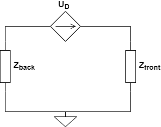
The following generic model circuit was shared in one of the earlier posts, for the acoustical part.

The impedance behind and in front of the diaphragm depicted by $Z_{back}$ and $Z_{front}$ respectively, are to be expanded based on the details of the driver that were identified.
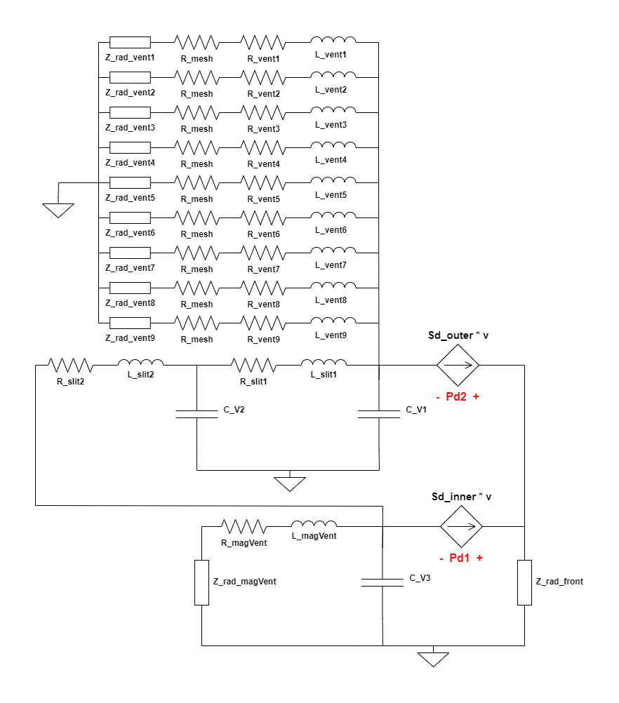
The complete electrical circuit, hence developed, representing the acoustical section of the driver is as follows,

| Component | Description |
| C_V1 | Acoustic Compliance of cavity of volume V1 |
| C_V2 | Acoustic Compliance of cavity of volume V2 |
| C_V3 | Acoustic Compliance of cavity of volume V3 |
| L_magVent | Acoustic Mass of the vent in the magnet |
| R_magVent | Acoustic Losses in the vent in the magnet |
| L_slit1 | Acoustic Mass of slit-1 |
| R_slit1 | Acoustic Losses in slit-1 |
| L_slit2 | Acoustic Mass of slit-2 |
| R_slit2 | Acoustic Losses in slit-2 |
| L_vent* | Acoustic Mass of the venting hole(s) in the driver’s body at the back |
| R_vent* | Acoustic Losses in the venting hole(s) in the driver’s body at the back |
| R_mesh | Acoustic Resistance of the paper/fabric mesh stuck on the venting holes at the back of the driver |
| Z_rad_vent* | Radiation Impedance seen by each venting hole(s) at the back of the driver |
| Z_rad_magVent | Radiation Impedance seen by the vent in the magnet |
| Z_rad_front | Radiation Impedance seen by the driver diaphragm radiating into free field |
| Pd1 | Acoustic pressure/voltage difference between the front and back of the part of the diaphragm of area = Sd_inner |
| Pd2 | Acoustic pressure/voltage difference between the front and back of the part of the diaphragm of area = Sd_outer |
All the radiation impedance blocks, which are named as Z_rad_xxxx are to be replaced by the full circuit as discussed in post #8. Note that each venting hole at the back has it’s own radiation impedance which has component values calculated based on the radius of the circular opening of each vent. Since each vent hole is of the same dimension, the radiation impedance circuit component values would be the same. However, each hole represents a piston which sees its own radiation impedance; hence, the separate dedicated Z_rad_vent* component for each vent in the circuit. The acoustic resistance of the mesh, R_mesh, that covers the 9 venting holes is the same since the material used is normally the same across all holes and the holes are all of the same circular area.
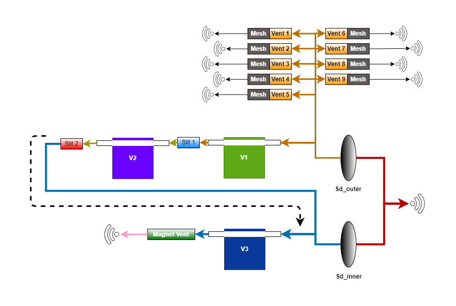
It might be worthwhile comparing the above circuit with the block diagram representation developed in the previous post and see how the connections correlate between the electrical circuit and the block diagram representation. Sharing the block diagram here for ease of reference.

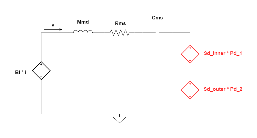
The mechanical circuit discussed in post #3 for the vacuum measurement scenario where the acoustic load is absent undergoes a change, now that the acoustical section is introduced. It’s mostly the same except for the introduction of 2 dependent voltage sources which model the application of an opposing force on the diaphragm owing to the air load that the diaphragm sees. The force/potential/voltage that it imposes is of the magnitude,
$S_D\ *\ Potential\ difference\ between\ front\ and\ back\ of\ the\ diaphragm$
Ideally, it’s only one voltage source that is placed in the circuit. However, in this case, due to the split of $S_D$ into 2 separate areas, we have 2 sources connected in series, for Sd_inner and Sd_outer, as in the circuit below.

1 Comment