For some time now, I have been wanting to dabble with some serious DSP hardware at the chip level so that, one day, I can build my own hardware for implementing active crossovers, EQs, filters, etc. for loudspeakers, room correction systems, etc. I wanted to go for the most powerful and popular solution in the market for audio applications which is obviously the SHARC family of processors from Analog Devices. While I was studying at DTU, I contemplated buying the SHARC Audio Module (SAM) kit sold by ADI to start playing with it. I wanted to know more about the hardware and see if I could get to try it out and play with it for a bit, before I made the purchase. Since I was a student then, I was wondering if a student discount was possible too. I wrote to the ADI Denmark sales department and got some communication going. Then the summer holidays happened and there was some radio silence for a couple of months. I got busy with exams and days went by. When I got a break from exams and coursework, I re-initiated the conversation on emails. Jonas Holm of ADI Denmark was kind enough to drive to where I worked my student job and hand over a brand new SHARC Audio module kit. I was taken by surprise by his gesture and I couldn’t hold my excitement. I cannot thank him enough for his gesture!
Life got even busier later and I hardly got the time to play with this cool piece of audio hardware. Finally, now the time has arrived to see what the SHARC module can do and what I can do with it. What I understand so far, is that, the whole evaluation platform and software package for this is very modular. You can plug and play adapter boards and also play with different software modules/libraries in conjunction with this hardware to achieve cool audio signal processing applications, create audio effects and such. In this blog post, I will be documenting the setup procedure as I go through it in steps, in reference to the online guide available on the ADI website – https://wiki.analog.com/resources/tools-software/sharc-audio-module. The source of this information is indeed the official ADI website. However, I found there were some minor variations between the tutorial online and the actual setup that I did at my side. This is mostly due to the versions of software and hardware being newer than when the tutorials were written by ADI. So, I will proceed with documenting the steps that I followed to set up my environment so that I have a reference for myself to come back to, if things turn sour at some point in the future.
1. Getting Started
The development environment used is called CCES – CrossCore Embedded Studio. This has to be downloaded and installed for the Windows operating system (if you use Windows too, like me). There is a license key which is required for using the development environment. This is also coupled to the emulator hardware, ICE-1000 in this case, so that other hardware cannot be used with this license key (that’s what I understand how this works).
This page covers all the details for doing all of the above -> https://wiki.analog.com/resources/tools-software/sharc-audio-module/gettingstarted
I did not have any confusions at this step. I basically followed everything as-is, as given in the above URL. Hope that should work fine for you too.
2. Bare Metal Framework
The base software that runs on the device is given as a code framework. More details here – https://wiki.analog.com/resources/tools-software/sharc-audio-module/baremetal
I’m following through with the tutorials here to run bare metal code on the hardware and learn how to use the CCES environment to build, debug and execute code on the hardware via the ICE-1000 JTAG interface.
Hardware setup
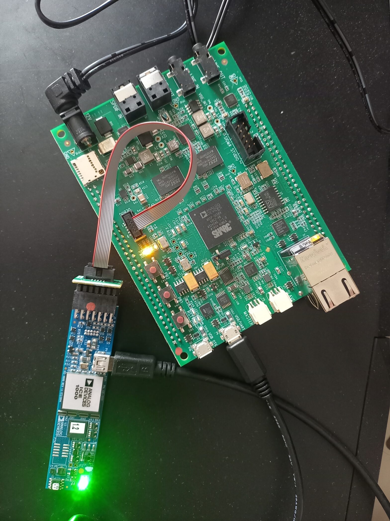
The hardware has been connected as seen on the cover picture of this post.
- The 12V power supply is connected to the DC barrel jack on one corner of the main board.
- The ICE 1000 module is itself connected to the computer via a USB Type-A to Mini-B cable.
- ICE-1000 has a relay-mate cable which plugs in, into the connector marked DEBUG on the SAM board.
- A micro USB cable is connected to the USB/UART port available on the SAM board which in turn connects it to the computer. This opens a serial interface to the SAM board which spits out log messages from the Bare Metal Framework to a terminal software application like TeraTerm running on the computer.
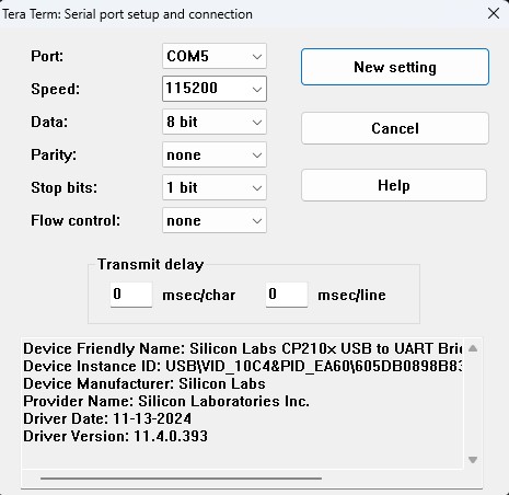
- The baud rate for this connection = 115200
- The drivers for the USB<->UART interface are obtained from here – https://www.silabs.com/developer-tools/usb-to-uart-bridge-vcp-drivers?tab=downloads
- The installation of drivers is done by unzipping the driver ZIP package contents downloaded from the link above and Right Click-ing on silabser.inf file and click Install.
- To confirm successful installation, open Device Manager and check the Ports (COM & LPT) list to see if a COM port has been assigned.

- The TeraTerm Serial Port settings are as follows:
Building and Debugging on CCES
Using CCES to build and debug code is as described in this official video:
Alternative link : https://www.analog.com/en/resources/media-center/videos/5858373742001.html
Once all is setup and done, the audio pipeline runs as an infinite loop taking in audio, processing it and outputting it. As per the tutorial video, they say, they have this logic running on the basic beginner application which is enabled by the Bare Metal Framework. Since I did not have 3.5mm stereo cables with me already, I could not test this out. I will soon be procuring the necessary cables and have some fun with this hardware.
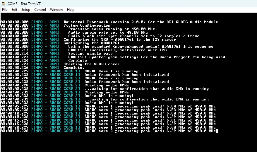
With the USB/UART connection plugged in to the computer and TeraTerm opened with the right COM port and baud rate settings as discussed above, the framework dumps continuous string of log messages which are as in the screenshot below, when the program is loaded on all the 3 cores (ARM, SHARC-1, SHARC-2) of the processor and running.