In the previous post, how different elementary structural shapes/forms are represented in the lumped electrical circuit was discussed. The mathematical expressions for calculating corresponding component values were also discussed. It’s time to advance further into converting the shapes/parts identified in the Ole Wolff driver that’s being studied here and see how they connect with each other to form the final lumped circuit.
In the previous post, I made a mistake in the way I explained the concept of the acoustical compliance capacitor. Rene Christensen, CEO of Acculution ApS, once again, very promptly pointed out the mistake and diligently explained to me what I was doing wrong and what the principle actually is. Rene also thoroughly checked all the expressions and equations. I consider myself immensely fortunate to have such a pro-reviewer to check my work out and provide top notch feedback. Thanks a ton, Rene! 🙏 So, I will start with explaining the concept, the ‘corrected’ version, before delving into the next steps of the project. While getting the concept clarified and better understood, I was very curious to see if ChatGPT could help with explaining acoustics concepts to me. So, I sought help from ChatGPT to summarize a lot of the concepts and asked it to explain to me in a concise and neat manner, to see what it does. I must say, I was super surprised by how much acoustics ChatGPT understands/knows! Simply Amazing!!!
The correction
I stated that the acoustic compliance behavior of an air volume enclosed within a cavity is modelled as a capacitor with one of the terminals grounded electrically. I stated the reason for this grounding is due to the rigid wall assumption which leads to the acoustic pressure on the walls being Zero. This part about the acoustic pressure being zero on a rigid wall, is where I am wrong. It’s not the pressure, but the particle velocity normal (perpendicular) to the surface of wall that is ZERO, when the walls are considered to be RIGID. The RIGID walls prevent movement of air molecules where as more and more particles get pressed against the wall surface which causes some pressure to build up. So the pressure could very well vary at the surface even though the particle velocity is zero in the normal direction. A zero particle velocity would equate to a zero current in the electrical circuit, in the impedance analogy. In that case, that means the capacitor terminals are OPEN (no connection), so that, NO current flows. However, in the case of the OPEN circuit, there could be a finite pressure/voltage at the terminals even though the current is Zero. A zero pressure is possible only if there is a short circuit across the terminals of the capacitor, in which case, the velocity/current is also zero. But this is NOT the rigid wall condition.
The attribute/property of the enclosed air volume that is modelled as the capacitor is the stiffness (inverse of compliance) of the air volume which is related to pressure by the differential velocity. Differential velocity is the difference between the velocities at the input of the cavity and the other end/exit of the cavity. In this case, the other end is a rigid wall, due to which the velocity at the exit is zero. Hence the differential velocity here becomes
Differential velocity = input velocity – exit velocity = input velocity – 0 = Input velocity
So this means, that the velocity at the input due to sound waves entering the cavity translates into a corresponding pressure variation due to the stiffness of the air in the cavity.
So, why is one terminal GROUNDed?
The grounding of one of the terminals of the capacitor in the electrical circuit is NOT to be understood as the rigid wall terminal being set to zero pressure. This capacitor terminal that is grounded does not necessarily represent the rigid wall of the cavity. Pressure (variations) in the cavity are defined in a relative sense with respect to the ambient pressure. Hence the pressure at the grounded terminal is at a ZERO “relative” pressure with respect to the ambient pressure. The other terminal which is left OPEN, models the pressure variations in relation to the ambient pressure. (This is the case, because the IMPEDANCE analogy is being followed for the modelling here.)
Handling Effective Radiation Area, $S_D$
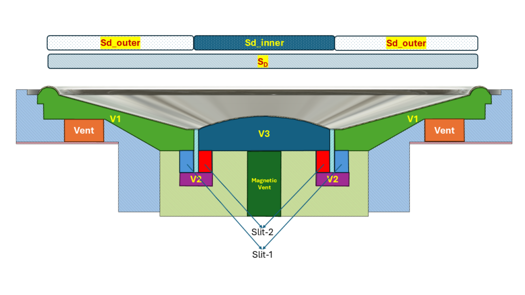
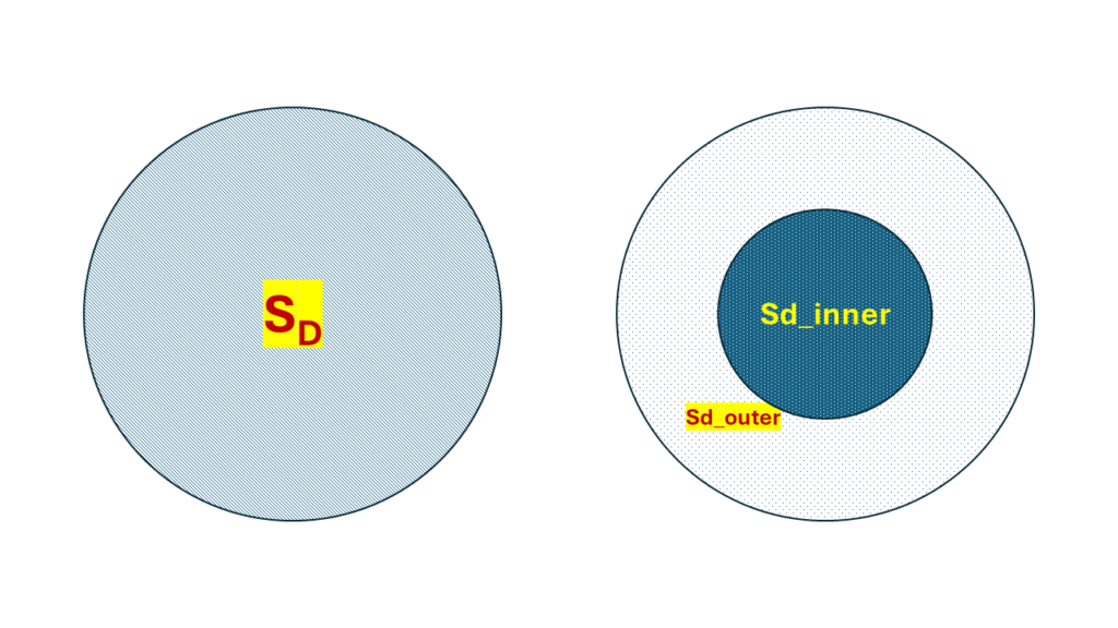
As was seen in one of the earlier posts, there were 2 paths for air flow behind the diaphragm that were identified. To be able to model the 2 different paths, the approach I’m going to follow in this project is to break the effective radiation area of the piston into 2 segments. One being the central, inner part of the piston whose area is roughly that of the circle of radius of that of the voice coil, since this is the part of the diaphragm which impinges on the volume of the cavity marked $V3$. The other part is the area of the piston surrounding this central circle, which impinges on the cavity of volume, $V1$. Let’s call the inner area, $Sd_{inner}$ and the surrounding area, $Sd_{outer}$. To make it easier to understand, the following illustration has been made.


The circle on the left shows the total effective radiation area of the piston, $S_D$ and it is split into 2 areas as seen on the right, such that:
$S_D = Sd\_inner + Sd\_outer$
In the lumped model, these 2 parts would be modelled as 2 separate dependent current sources with 2 different volume velocities corresponding to $Sd_{outer} \cdot velocity\ of\ the\ diaphragm$ and $Sd_{inner} \cdot velocity\ of\ the\ diaphragm$.
As per the definition of the Effective Radiation Area discussed in an earlier post, the value of this parameter is an estimated value that when used in the model gives an output response that resembles the actual measured data. Different methods could be adopted to find this value. Here I’m using this as a variable that would be estimated by curve fitting to measurement data. To simplify the parameter estimation step, $Sd\_inner$ could be regarded as a fixed value which could be computed as the area of a circle whose radius is that of the voice coil, while $Sd\_outer$ is taken as the variable component which would be estimated by fitting later.
Acoustic Block Diagram of the Driver
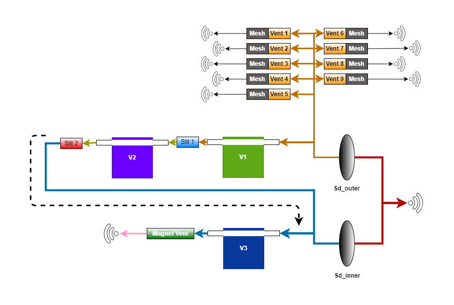
Before developing the lumped model electrical circuit diagram, a block diagram representation of the acoustical model of the circuit is laid out here. This diagram shows the acoustical elements (cavity volumes, acoustic masses, acoustic losses) separated out and how they are connected with each other in the case of the driver being studied here. The electrical circuit would then be derived by just replacing the acoustic elements with the corresponding electrical circuit components as discussed in the previous post.

Preparing a sketch of the block diagram like this, of the acoustic system, is often helpful in checking and verifying if all elements of the acoustic system have been identified correctly and if they are connected properly with respect to each other. Drawing the electrical circuit as the next step, is then much easier. Also by comparing the electrical circuit with this block diagram is a good way of verifying if the modelling is correct. The arrows/branches with the same color are on the same potential/voltage/acoustic pressure.
The cavity volumes appear to have 2 tubes connected to them on the left and the right sides. They are not exactly tubes. Those 2 rectangles on either side of each cavity volume are just ports for representation, to connect the volume and note that, both of them are also at the same acoustic pressure level. (Notice the color of arrows before and after the cavity volumes. They are with the same color representing same potential w.r.t the ambient reference pressure.)
The WIFI logos put in the drawing are to indicate sound radiation into the free field. These logos would be translated into corresponding radiation impedance circuits as was described in the previous post. Though the same WIFI logo symbol is used everywhere, where the radiation is happening around the driver, the specific values of the radiation impedance circuit’s components (Ma1, Ra1, Ra2, Ca1) could vary from one to the other due to the radius of the radiating piston element changing from case to case. For example, the 9 vents in the back of the driver body have a different radial dimension as compared to the vent in the magnet and this is all very different from the dimensions of the whole diaphragm radiating in the front of the driver. The same symbol was used to show the radiating elements for convenience and simply because I couldn’t find enough ‘different’ symbols in the DRAW.IO library. 😀
The diaphragm has been broken down into 2 separate diaphragms of 2 areas as was discussed before. Also note that, for the 9 vents at the back of the driver’s body, the resistance of the tuning mesh is also attached at the outlet of the vents marked by the brown colored boxes titled “Mesh”, in the block diagram. The slits are modelled as tubes with an acoustic mass and some losses.
1 Comment