In the previous posts, the electro-mechanical sections of the driver’s lumped element were characterized and the parameters estimated from measurement data (manufacturer provided), by curve fitting. Now that, that is fixed, it’s time to look at the acoustical part of the model circuit. Generally, the acoustical section of the model is characterized as a Controlled Current Source, generating a Volume Velocity $U_D$, which is loaded by 2 impedances, one for the front and the other for the back side of the diaphragm. The transduction factor between mech and acoustical domains, the Effective Radiation area of the diaphragm, $S_d$ (unit – $m^2$) is multiplied with the mechanical linear velocity of movement of the diaphragm, $v$ (unit – $\frac{m}{s}$), to obtain the Volume Velocity, $U_D$ (unit – $\frac{m^3}{s}$). ($v$ is represented by the electrical current flowing through the mechanical section circuit of the model, as was discussed in the previous chapters.)
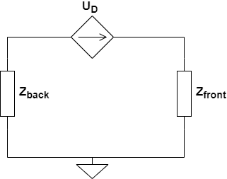
The above circuit is a generic representation of the acoustic section of the lumped model of a driver. The task now is to derive/find what $Z_{back}$ and $Z_{front}$ impedances are, based on the structural design of the driver. As was discussed before, the flow profile of air within and around the driver due to the movement of the diaphragm of the driver is the key aspect to be studied to deduce the net acoustic impedance seen by the driver. The hope is thus to find if we can characterize the perturbations (peaks and dips) in the electrical impedance data, found after the first dominant peak.
Before looking into the air flow profile in the driver, it would be helpful to get acquainted with the parts of the driver, since those names would repeatedly be referred to, as we progress.
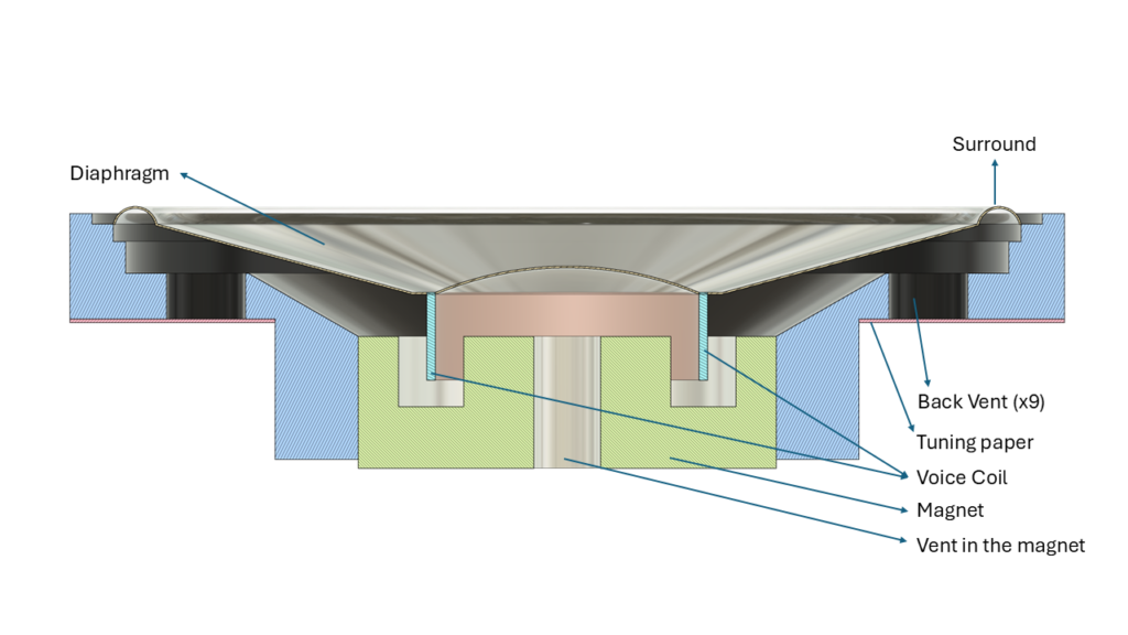
(The generic loudspeaker driver that I modelled from scratch has been used for the sake of illustration here. This is NOT the actual Ole Wolff driver. This generic model has been used since the manufacturer-provided CAD model has most of these internal details hidden.)
In microspeaker-type drivers, like the one seen here, the diaphragm and the surround are one unified construction. Even the central dome like structure which is normally known as the ‘dust cap’ in conventional loudspeaker drivers, is molded as part of the diaphragm structure here. This is unlike bigger speaker drivers where each of these are separate parts that are glued together in production. The voice coil is stuck to this diaphragm and is placed within the magnetic gap. Since the magnets are relatively much smaller as compared to large drivers, the magnetic field strength is much smaller leading to a very low value for the Force Factor, $Bl$. The magnet usually has a cylindrical vent in the centre which lets air flow through it. Sometimes, some drivers have a mesh or tuning paper attached around the exit of the hole acting as an acoustic damper. Manufacturers often use meshes of varying air flow resistance in a way that it can be used to tune the response of the driver by increasing or decreasing the amount of damping in the system. On the outer periphery of the driver’s structure there are cylindrical vents covered by tuning mesh/paper which again provide some control to the manufacturer in tuning the driver characteristics. In the driver being studied here, there are 9 such outlets at the back side of the driver along the outer periphery.
Air flow profile
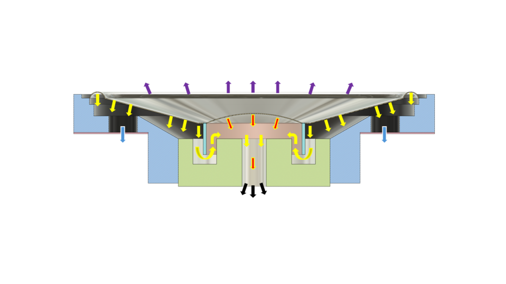
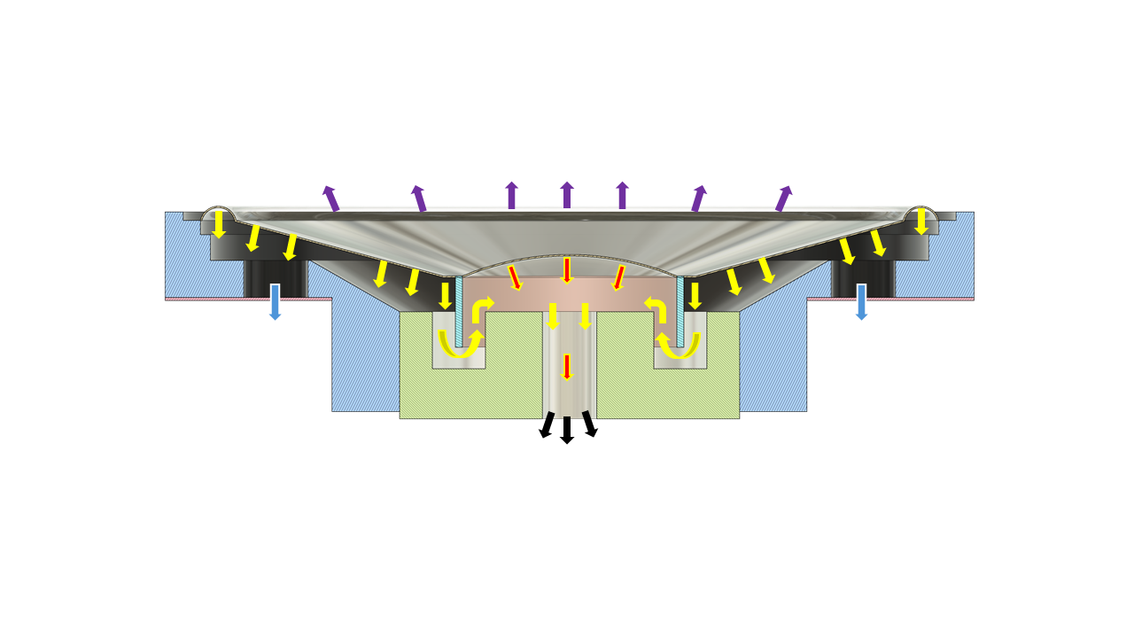
I prepared an illustration based on the same generic model of a microspeaker driver, to show how air moves in and around the driver when the diaphragm is set in motion. (Note: All arrows used are shown as being uni-directional. This is only for illustration purposes and to keep it simple. Depending on the direction of movement of the diaphragm, the air movement happens in both directions.)
From the figure above, it can be seen that, in the front side of driver, the diaphragm is radiating into free field as denoted by the purple arrows (assuming the driver is placed in an anechoic space without any obstructions around it). The situation behind the diaphragm is quite different though. There is air movement which finally exits the driver into the free field behind the driver. However, air takes a very convoluted path and many such different paths before it exits the driver from the back side. To begin with, let us look at the yellow arrows alone. The path is the air pushed by the backside of the diaphragm enters a large cavity (volume) behind the diaphragm, which then makes its way though the outer ring of the magnetic gap to enter another small volume which is formed by the magnetic assembly. Then, air further flows through the inner ring of the magnetic gap to enter the cavity under the dome like region of the diaphragm and finally travelling through the vent in the magnet and exiting the driver structure into the free-field. The Red arrows indicate the air flow set out due to the central dome like part of the diaphragm which travels through the vent in the magnet and exits the driver assembly. The combined output of these 2 paths of air is shown by the Black colored arrows. Additionally, there is another path where the air exits the driver through the cylindrical vents in the driver casing, indicated by purple arrows.
Driver components for forming LUMPED elements
Here comes the main part. Now, we have to identify parts of the driver that are eligible to be lumped into components that would constitute the acoustic section of the model. Cavity volumes, slits, vents, etc. are lumped and mapped into corresponding R-L-C components based on the idea that the physical variable, either the acoustic pressure or particle velocity, remains constant at any point within the confines of the structural element considered. There are empirical equations available for each of these structural shapes/elements which are derived for specific conditions. Even though, the elements in our example, need not always have the same conditions as mandated by the empirical formulations, we could still use them to a reasonable degree of accuracy atleast to arrive at starting guess values for the fitting algorithm. This is how it’s commonly done in endeavors like this (as far as I know) and that is the approach I will be taking here too.
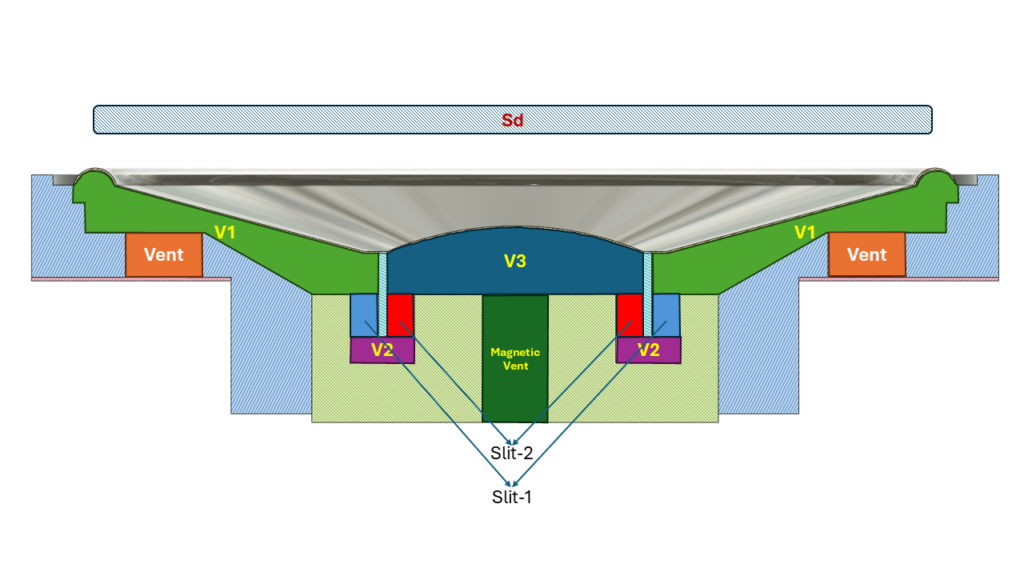
Based on the air flow within the driver, as discussed in the previous section, I have classified and segregated the part of the driver behind the diaphragm into the following cavities, vents, etc.
- V1 – Volume of the cavity right under the part of the diaphragm and surround (except the central dome region) encapsulated by the driver’s casing.
- V2 – Volume of the small cavity within the magnet assembly under the voice coil.
- V3 – Volume of the cavity under the central dome like element of the diaphragm encapsulated by the inner walls of the voice coil.
- Vent – The cylindrical holes in the driver casing.
- Slit-1, Slit-2 – The narrow regions/gaps between voice coil and the walls of the magnetic assembly. Slit-1 is the outer gap. Slit-2 is the inner gap.
- Magnetic Vent – The cylindrical hole in the centre of the magnet assembly.
- Sd – This is the effective radiation area as discussed before. This is not necessarily the entire surface area of the diaphragm. This is the surface area of a (imaginary) flat circular piston which has an equivalent amount of radiation as that of the diaphragm, but fully normal to the piston surface.
The below figure illustrates each of the above mentioned sections in the driver.
In the next post, we shall look at the empirical expressions for computing parameter values.
2 Comments